RCCN WeChat QrCode
 Mobile WebSite
What is a linear regulated power supply? How does it work? According to the working state of the regulator tube, we often divide the regulated power supply into two categories: linear regulated power supply and switching regulated power supply. In addition, there is a small power supply that uses a voltage regulator tube. The linear regulated power supply mentioned here refers to the DC regulated power supply in which the regulator tube works in a linear state. When the adjustment tube works in a linear state, it can be understood as follows: RW (see the analysis below) is continuously variable, that is, linear. But in the switching power supply, it is different. The switching tube (in the switching power supply, we generally call the adjusting tube as the switching tube) is working in two states: on-the resistance is very small; off-the resistance is very high Big. The tube working in the switch state is obviously not linear.
Linear stabilized power supply is a type of DC stabilized power supply that was used earlier. The characteristics of the linear regulated DC power supply are: the output voltage is lower than the input voltage; the response speed is fast, the output ripple is small; the noise generated by the work is low; the efficiency is low (the LDO that is often seen now is to solve the efficiency problem) ; High heat generation (especially high-power power supplies), which indirectly adds thermal noise to the system.
Working principle: Let's first use the figure below to illustrate the principle of voltage regulation by a linear regulated power supply. As shown in the figure below, the variable resistor RW and the load resistor RL form a voltage divider circuit,
The output voltage is: Uo=Ui×RL/(RW+RL),
Therefore, by adjusting the size of RW, the output voltage can be changed. Please note that in this formula, if we only look at the change in the value of the adjustable resistance RW, the output of Uo is not linear, but if we look at RW and RL together, it is linear. Also note that our picture does not draw the leading end of the RW to the left, but to the right. Although there is no difference from the formula, it is painted on the right, but it reflects the concept of "sampling" and "feedback"-the actual power supply, most of them work in the mode of sampling and feedback Below, the feedforward method is rarely used, or it is used, and it is only an auxiliary method.
Let's continue: If we use a triode or field effect tube instead of the varistor in the picture, and by detecting the size of the output voltage, we can control the resistance of this "varistor" so that the output voltage remains constant, so that we can To achieve the purpose of voltage stabilization. This triode or field effect tube is used to adjust the voltage output, so it is called an adjustment tube.
As shown in Figure 1, because the regulator tube is connected in series between the power supply and the load, it is called a series regulated power supply. Correspondingly, there is also a shunt-type stabilized power supply, which is to adjust the output voltage by connecting a regulator tube in parallel with the load. A typical reference regulator TL431 is a shunt-type regulator. The so-called parallel means that, like the voltage regulator tube in Figure 2, the attenuation amplifier tube emitter voltage is "stable" through shunting. Perhaps this figure does not let you see that it is "parallel" at once, but Take a closer look, it is true. However, everyone should pay attention to this: the voltage regulator tube here works in its non-linear region. Therefore, if you think it is a power supply, it is also a non-linear power supply. In order to make it easier for everyone to understand, let's look back and look for a reasonable picture until we can understand it concisely.
Since the adjustment tube is equivalent to a resistor, it will generate heat when the current flows through the resistance, so the adjustment tube working in a linear state will generally generate a lot of heat, resulting in low efficiency. This is one of the most important shortcomings of the linear regulated power supply. For a more detailed understanding of the linear regulated power supply, please refer to the analog electronic circuit textbook. Here we are mainly to help you clarify these concepts and the relationship between them.
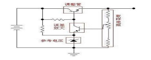
Generally speaking, the linear regulated power supply is composed of several basic parts such as a regulator tube, a reference voltage, a sampling circuit, and an error amplifier circuit. It may also include some parts such as protection circuits, start-up circuits and so on. The following figure is a relatively simple linear stabilized power supply principle diagram (schematic diagram, omitting filter capacitors and other components). The sampling resistor samples the output voltage and compares it with the reference voltage. The comparison result is amplified by the error amplifier circuit to control the adjustment tube. The degree of conduction keeps the output voltage stable.
Commonly used linear series stabilized power supply chips are: 78XX series (positive voltage type), 79XX series (negative voltage type) (in actual products, XX is represented by numbers, and what is XX is the output voltage. For example, 7805, output voltage 5V); LM317 (adjustable positive voltage type), LM337 (adjustable negative voltage type); 1117 (low dropout type, there are many models, the voltage value is expressed by the mantissa. For example, 1117-3.3 is 3.3V, 1117-ADJ It is adjustable).