RCCN WeChat QrCode
 Mobile WebSite
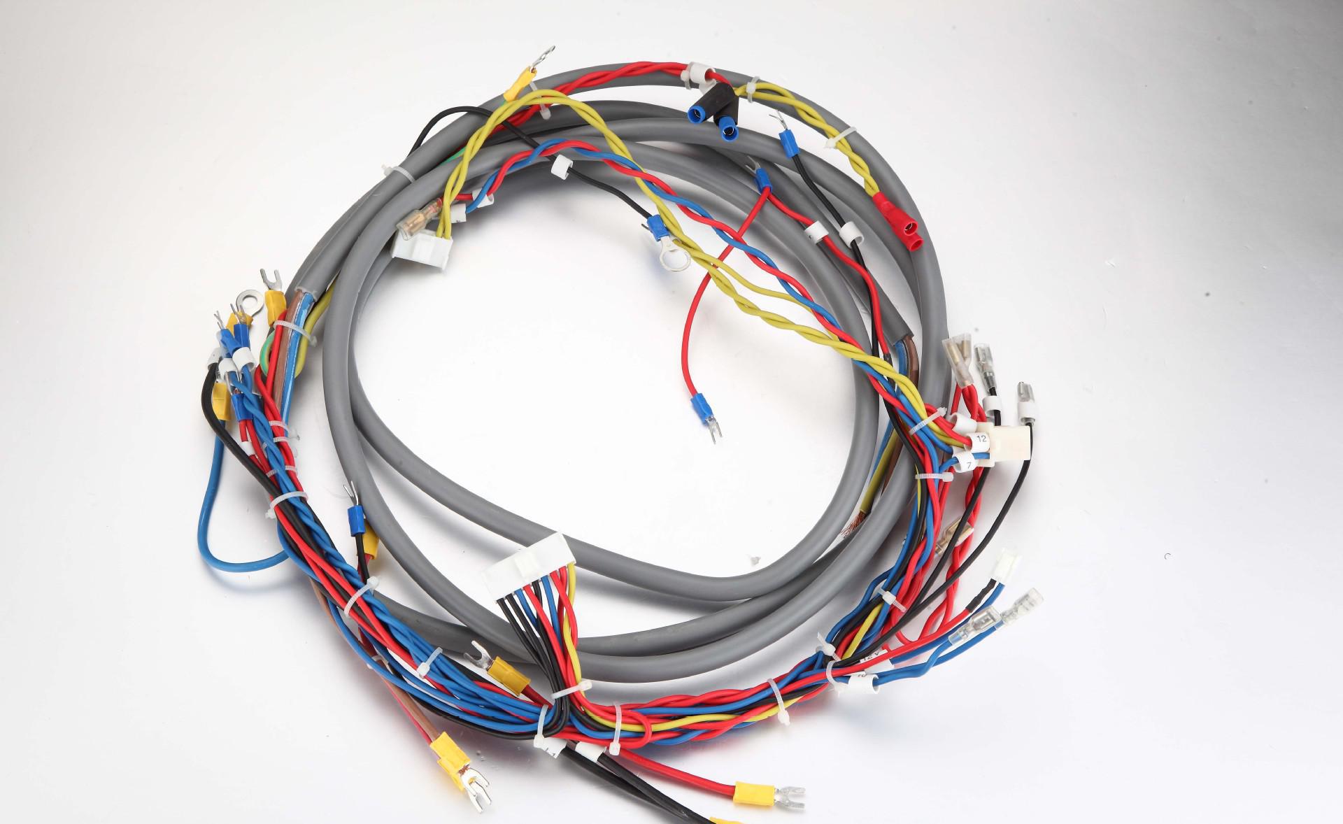
Voltage and current, first determine the maximum current line, according to the current to determine the cross-sectional area of the harness, determine the cross-sectional area after determining the length of the harness, and then calculate the total current to determine the main fuse fuse current, select the fuse. After selecting the good use of three-dimensional software design wiring harness, according to the three-dimensional harness production line diagram.
2, the sensor
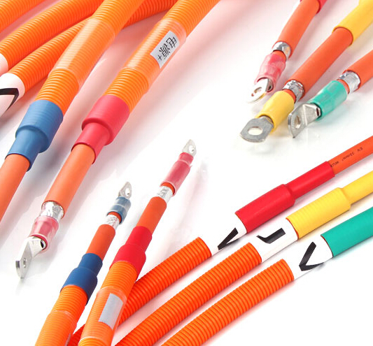
The working voltage and current of the sensor are small, usually milliampere level, and select small diameter, such as cross-sectional area of 0.35 mm2, but taking into account the wiring harness tensile, anti-fracture performance and durability, usually choose Such as cross-sectional area of 0. 5mm2 wire. It should be noted that, in order to improve the electromagnetic compatibility (EMC) and electromagnetic interference (EM I) performance, for the magnetoelectric sensor to use twisted pair, shielded wire and so on. When using twisted pair, the general 33 spiral / m, such as the engine speed sensor and cam position sensor. In the cbr engine has ECT, TP, MAP, CAP, CKP several major signal lines, in these signal lines are in the mA level, the maximum voltage of 5V. In the wiring harness selection are generally selected 0.5mm2 cable.
AEX cable allows voltage and voltage drop
AVX, AEX are the two main products of the Japanese cable. Since the allowable operating temperature of the two cables includes the operating temperature of the engine cable, the following data is calculated based on these two tables.
Wire cross-sectional area calculation formula: A = IpL / U A ---- conductor cross-sectional area I ------ load current P ----- copper resistivity L ----- wire length
U ----- Maximum voltage drop allowed Maximum voltage (V) Operating resistance (ohms) Maximum current (A) ECT 5 650 7.69x10 ³ TP 5 3200 1.56x10 ³ MAP 5 6000 0.83x10 ³ CAM 5 490 10.2x10 ~³ CKP 5 430 11.6x10 ~ ³ Ignition coil 12 1.6 7.5 Fuel injector
According to the known current and copper resistivity, the signal voltage drop is 500mv maximum, the cable cross-sectional area is 0.5mm2,
Calculate the minimum available length of each sensor. (Mm) Maximum permissible voltage drop (V) Lead length L (m) ECT 0.5 0.5 1230 TP 0.5 0.5 6064 MAP 0.5 0.5 11398 CAM 0.5 0.5 927 CKP
According to the above calculation data, for the sensor, the greater impact on the signal is not the length of the wiring harness, but other reasons.
Signal cable will choose 0.5 square feet, high temperature 120 degrees Celsius, two-color line.