RCCN WeChat QrCode
 Mobile WebSite
Circuit design requirements:
1, power distribution:
1.1 Location assignment:
A, power supply location allocation using the nearest principle: general electrical box is divided into instruments, front cabin, battery 3, power distribution using the nearest principle to reduce the number of wires used, such as: low beam, high beam, front fog lights Are in the front compartment position, so the low beam, high beam, front fog lamp relay and fuse are placed in the front compartment electrical box.
B, battery electrical box mainly placed main power supply.
C, a few special placement requirements:
(1) The turn signal relay must be placed in the cockpit so that the driver can sense the sound of the turn signal relay.
The brake light relay must be placed in the front compartment electrical box, causing noise to the driver and crew in the cockpit, or by using a mute relay in the cockpit. But as far as possible the use of the way before the preshipped electrical box, unless the customer asked to use the way to put the cabin.

1.2 System allocation:
(1) constant power supply distribution:
A, the distribution of power in the often power supply is still off the ignition switch still need to work equipment: indoor delay lights, anti-theft system, luggage lights, speakers, small lights (position lights), diagnostic systems, backup power, brake lights, Controller memory power, alarm lights and a variety of electrical system power supply and so on
B, the distribution of power in the regular power also includes the ignition switch control directly connected to the original power of the original equipment: cooling fan motor, blower, near light, high light, fog lamp, wiper, after defrost, starter, Compressors, pumps and so on.
(2) ignition switch power distribution:
ACC file: equipment to be disconnected when the engine is started (sound system, cigarette lighter, power outlet, electric rearview mirror, etc.)
IG2: Equipment to be disconnected when the engine is started (air conditioning blower control power supply, electric heating defrost, electric sunroof, seat heating, electric windows, wiper sprinkler systems, etc.)
IG1: the ON file, the file in the ST open, still power supply, the engine can be used to start the equipment to be assigned to this file (instrument, EFI ECU, ABS, BCM, airbags, reversing lights, etc.)
ST: Start the motor, release the key back to the ON position, in this position when the ACC and IGN2 file load power, so that more power to start. The gear is only supplied to the starter motor and is not supplied to other equipment.
Note: The ignition switch of the file carrying current requirements, so the allocation of equipment to calculate the current distribution of the current. The total current of the equipment assigned to each file can not exceed the carrying current of each gear.
Ignition switch off diagram:
2, ground distribution:
A, inductive load to be grounded separately: cooling fan, blower and so on
B, the control module to be grounded separately: EFI ECU, ABS, ESP, EPS, TCU, TPMS, AVM, BCM, MP5
C, the sensor must be grounded separately: fuel sensor, water temperature sensor.
3, the distribution and selection of relays:
3.1 Distribution of relays:
The role of the commonly used relay is a small current control of the role of high current, the relay is used to protect the switch contacts, if the switch contacts to withstand the load current to meet the load rated current can not relay protection. So the resistance of the switch contacts can not meet the load rated current when you need to use the relay to small current control projection large current.
A, need to use the relay load: cooling fan, blower, near light, high light, front fog lights, small lights, brake lights, front wiper, the main relay, pumps, compressors, speakers
B, part of the need to control the load of the strategy need to select the relay: rear wiper, reversing lights, washing, ACC, IG1, IG2.
3.2 Relay selection requirements:
A, contact form: According to the control requirements of the circuit system to determine the relay contact form (a contact, two contacts, normally open, normally closed, etc.), and then according to the rated load current and other requirements (electrical parameters, Mode 30 for the electrical input, 87 for the output, 85 for the coil is positive, 86 for the coil) to select the final relay specifications.
B, the working voltage range: the need to develop models according to the power supply voltage requirements to choose, the current general 12V and 24V;
C, the choice of electrical life: According to the functional requirements of different electrical life is also different, the general life of the relay can be 1 × 10⁵ times;
D, the choice of current load: According to the rated current of the electrical equipment to use the corresponding rated current relay, the relay rated current depends on the contact load performance (contact material is generally AgSnO), relay rated current of 70% should not Less than the normal working current of the load;
E, the temperature range: According to the location of the load relay to determine the selection of the relay temperature parameters: such as assembly in the room,
Temperature range: -40 ℃ ~ +85 ℃; such as assembled in the front cabin, temperature range -40 ℃ ~ +125 ℃.
F, dry and wet areas of the points: the former cabin selection waterproof, cockpit can choose not waterproof.
4, the fuse distribution and selection:
4.1 Assignment of fuses:
A, safety-related systems can not be shared with other systems Insurance: airbag systems, ABS, EFI ECU, brake lights, near light, high beam, TCU, TPMS, AVM, pumps and so on.
B, dirty current, high current electrical appliances using separate insurance: blower, fan, window, defrost, compressor and so on.
C, high and low current loop (current difference of more than 5A) does not share an insurance.
D, dirty power definition: inductive and capacitive load, motor load, relay electric side, PWM, speed sensor, radio (high power amplifier is applied), cigarette lighter, etc .;
E, the distribution of slow-melting fuses and fast-melting fuses:
The choice of slow-melting, fast-melting fuse should be based on the performance of the load on the protected circuit, or if the fusing time of the fast-acting fuse exceeds the peak current time of the load, the fast-acting fuse can be selected. If it is not satisfied, Fuse, general motor load selection Slow fuse, such as: electric windows, cooling fans, blowers, ABS, starter, EPS, ESP, EPB, after defrosting. Primary fuse to use slow melting fuse.
4.2 Selection of fuses:
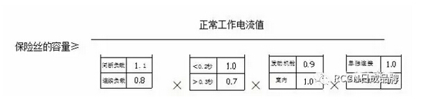
The role of the fuse is to protect the wire and electrical appliances, with the rated power of the electrical work according to I work = P / U calculated at room temperature (25 ℃) under the rated current of the fuse for the electrical working current of 135%, when the ambient temperature When the fuse is raised, the current carrying capacity of the fuse will drop. The empirical formula of the fuse is calculated as follows:
A, the fuse capacity to determine:
Description:
Continuous load: working time in 10 seconds or more, intermittent load: working time in 10 seconds or less;
Peak current time: If the time of peak current <1.0 seconds for the time 1.0, such as time> 0.3 seconds for the 0.7; (Note: combined with the current design level of electrical devices, tentative peak current time> 0.3)
Load assembly area: If the layout is in the room is the coefficient of 1.0, such as arranged in the engine compartment is the coefficient of 0.9;
Fuse installation area: If the fuse is connected separately, the coefficient is 1.0, and if the fuse is installed in the fuse box, the coefficient is 0.9
For example: S12 speaker fuse: working current is 8A, then: FUSE capacity ≥ 8A ÷ [1.1 × 0.7 × 0.9 × 0.9] = 13A, according to the actual specifications of the fuse can choose 15A fuse to protect the line.
Design requirements: In the case of load and line overload, the load and the line no effect, in the load and the line short circuit case, the fuse will fuse, the line has no influence. Motor stall case, the line has no effect, the fuse will not blow.
5, the wire matching selection:
5.1 According to the temperature requirements of the selection of wires: cockpit selected 75 ℃, the front cabin engine around the selection of 100 ℃ wire, the engine selected 120 ℃ wire.
5.2 Select the wire according to the current:
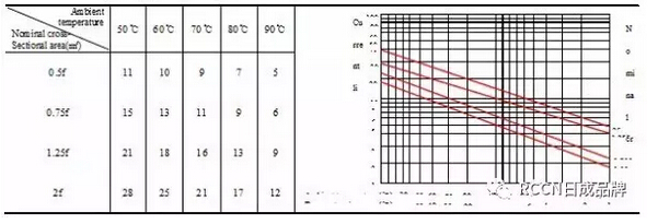
5.2.1 first by the formula I work = P / U to calculate the current of the electrical appliances, and then according to the following table conductor load current to choose.
AVSS conductor: Carrying current value at 70 ° C as the operating current value of the wire.

AVS Conductor: Carry current value at 70 ° C as the operating current value of the wire.
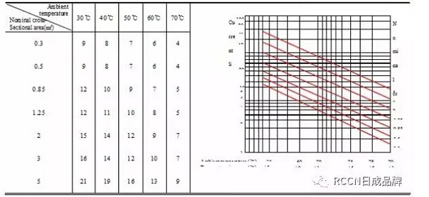
AV conductor: The carrying current value at 70 ° C is used as the operating current value of the wire.
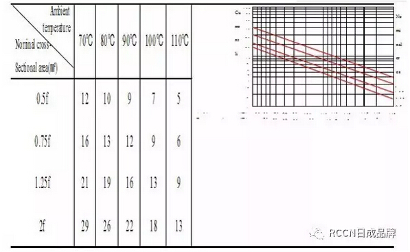
AVSSX: Carrying current value at 90 ° C as the constant operating current value of the wire.
AESSX: Carrying current value at 110 ° C as the periodic operating current value of the wire.
Through the above electrical system of the electrical parameters of the confirmation and the design of the working circuit, refer to the principle of selection of circuit protection components, the preparation of vehicle electrical load power distribution table, the list of specific format as follows:
Power distribution table
|
|
||||||||||||
|
Serial numberAssembly area |
|
Fuse capacity |
Insurance
|
power supply
|
load
|
Line diameter |
Take the point |
Load characteristics |
Working characteristics |
rated power |
Load current and fuse capacity ratio |
Remarks |
|
1 |
Front cabin |
30 |
JT(SLOW) |
30High speed fan |
|
2.5 |
G102 |
Motor load |
For a long time
|
160W |
45% |
|
|
2Front cabin |
|
10 |
MINI |
30 |
compressor |
0.85 |
G102 |
Motor load |
For a long time
|
60W |
50% |
|
|
3Front cabin |
|
15 |
MINI |
30Fuel pump |
|
2 |
G202 |
Motor load |
For a long time
|
~50W |
42% |
|
|
4 |
Front cabin |
20 |
MINI |
30 |
Low beam and high beam |
2 |
G101/G102 |
Lamp load |
For a long time
|
110W |
41.60% |
Turn light 220W |
|
5Dashboard |
|
10 |
MINI |
IGN1 |
ABS control unit |
o.5 |
G100 |
Control module |
short time
|
3.6W |
3% |
|
|
6 |
Dashboard |
15 |
MINI |
ACC |
Cigarette lighter) |
2.5 |
G207 |
Heating element |
short time
|
120W |
67% |
|
|
7Dashboard |
|
10 |
MINI |
30a |
Rear fog lights |
0.5 |
G202 |
Lamp load |
short time
|
21W |
18% |
|
|
9 |
Dashboard |
20 |
MINI |
50 |
Starter |
2.5 |
|
Lamp load |
short time
|
1.2KW |
|
Control line |
(Note: working time ≥ 10 sec. For long working time; working time ≤ 10 sec.: Short time work. JT (slow): slow fuse in the JT type; MINI: small fast fuse)
(3) wire color selection:
Different systems, different company standards inconsistent.
6, material selection design
1.1 Material selection should be selected according to different regions:
A, the temperature is different need to choose the different temperature of the material, the general selection of indoor wiring harness temperature 85 ℃ material, launched under the hood and the surrounding area selected temperature 100 ℃ material
B, outdoor selection of waterproof material, indoor can choose not waterproof material.
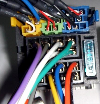
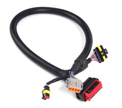
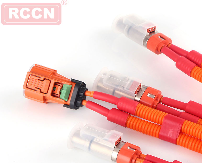
1.2, the choice of connectors:
The connector is the core part of the wiring harness. The performance of the connector directly determines the performance of the harness as a whole, and plays a decisive role in the stability and safety of the whole vehicle.
1.1.1 Selection of the connector To ensure good contact with the electrical parts, so that the contact resistance is reduced to the lowest, improve reliability, preferred with the second lock plug.
1.1.2 According to the cross-sectional area of the wire and the size of the current through the reasonable choice of connectors, different specifications of the connector can carry the current are generally as follows: 1 series, 10A or so; 2.2 or 3 series, 20A or so; 4.8 series , About 30A; 6.3 series, about 45A; 7.8 or 9.5 series, about 60A.
1.1.3 Engine compartment docking jacket, due to cabin temperature, humidity and there is a lot of corrosive gases and liquids, so be sure to choose waterproof jacket.
1.1.4 in the same harness if the same kind of jacket, the color must be different.
1.1.5 Based on the overall coordination of the appearance of the car, in the engine compartment should be preferred black or dark jacket.
1.1.6 In order to reduce the type and quantity of the jacket for the wiring harness, the mixing type is preferred, so that the assembly is easy to be fixed, but it is not suitable to select 50PIN connector.
1.1.7 multi-line connector as far as possible when the use of docking handle push and pull fixed way.
1.1.8 For high-performance airbags, ABS, ECU and other terminal fittings, should be preferred to use gold to ensure safety and reliability.
1.3, the whole car harness seal (rubber) design
1.3.1 The main parts of the rubber parts: the interface between the engine and the cab, the front cabin and cab interface (about 2), four (or back door) and the car interface, the tank at the entrance.
1.3.2 Rubber parts selection:
Commonly used materials are generally natural rubber, neoprene, silicone rubber, EPDM and so on.
A, the characteristics of natural rubber: a good elasticity and mechanical strength, excellent resistance to flexion, a higher tear strength and good cold resistance. Disadvantages: anti-aging is not good, not oil and ozone, flammable.
B, neoprene characteristics: resistance to ozone, heat aging, oil and other properties are better, with flame resistance and self-extinguishing; but low temperature resistance is not good.
C, silicone rubber characteristics: heat resistance, cold resistance and weather resistance is better; the disadvantage is not oil.
D, the characteristics of EPDM: weather resistance, ozone resistance, heat resistance, corrosion resistance, acid and alkali performance are better, and have high strength and high stretch rate; Disadvantages: poor adhesion, and flexibility No natural rubber is good, poor oil resistance.
E, in comparison, the overall performance of EPDM better, so the automotive wiring harness with rubber unless the customer special requirements, are selected EPDM material.
F, generally try to use the existing models used, can not be used to re-design.
1.4, wiring harness fixed design
1.4.1 wiring between the fixed point of not more than 300mm, fixed and the connector spacing of not more than 120mm.
1.4.2 fixed point as far as possible with anti-rotation fixed structure fixed
1.4.3 fixed material as far as possible with the cable type, special circumstances using tape binding way fixed.
1.4.4 fixed fixed structure of the INLINE need to consider the space, easy to operate, generally try to use the existing models used, can not be used to re-design.
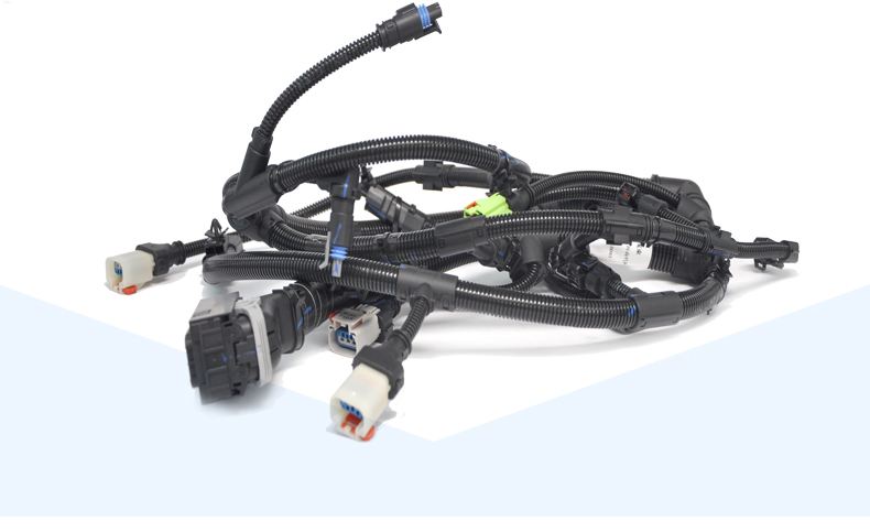
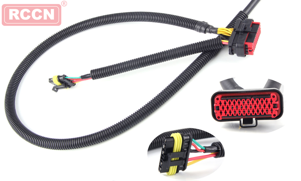
1.5, harness bandage design
1.5.1 harness outer wrapping effect: wear, flame retardant, anti-corrosion, to prevent interference, reduce noise, beautify the appearance.
1.5.2 Harness wrapping design requirements:
A, the engine harness work environment is bad, so all with high flame resistance, waterproof, high mechanical strength of the bellows bandage.
B, the front cabin work environment is relatively poor, most of the branches are also good flame retardant bandage, part of the branch with PVC pipe bandage.
C, instrument line work space is small, the environment is relatively good, the tape can be wrapped around the whole wrapped or wrapped.
D, the floor harness can be wrapped with tape, some anti-wear will be wrapped or wrapped with wear-resistant materials.
D, the door line and the roof line work space is small, and need to wear holes can be used to wear all the tape wrapped around
E, roof harness need empty column need to use tape all wrapped around
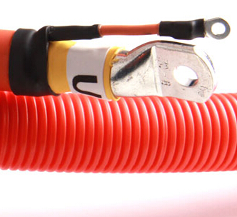
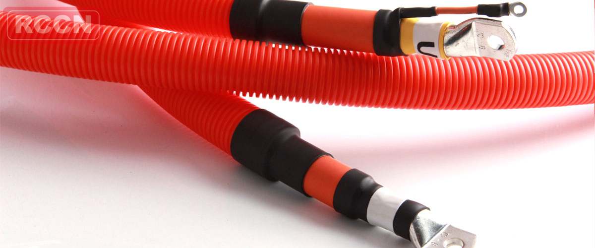
F, the battery cathode wiring harness needs to be insulated, so need to use bellows all wrapped or wrapped around.
G, battery negative harness can be without bellows and tape bandage.
1.5.3 selection of dressing material
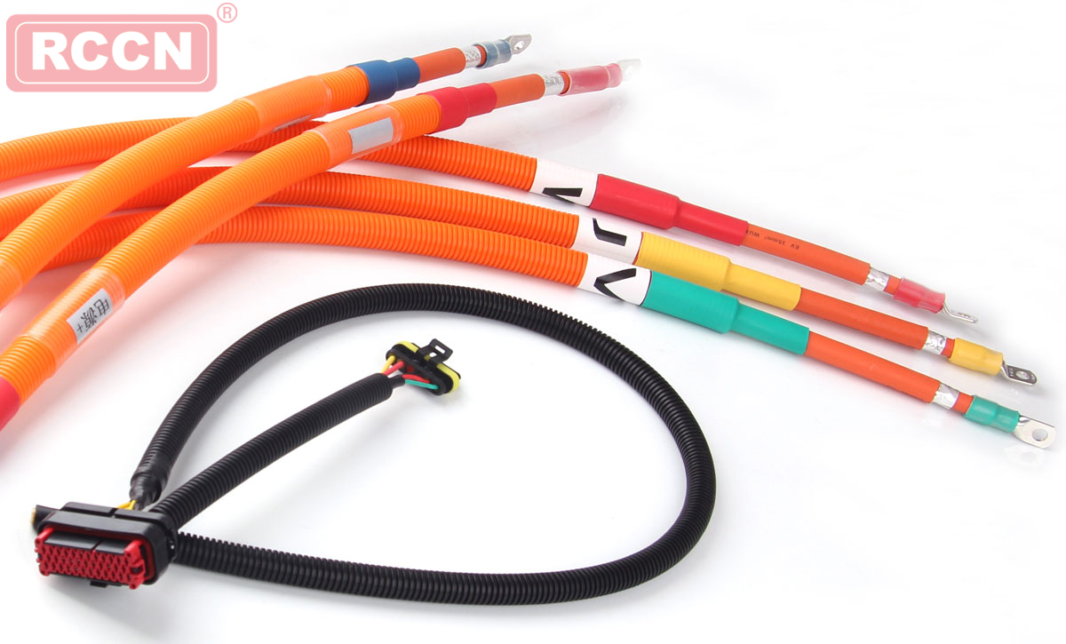
A. Bellows
Are currently using PP corrugated pipe, different functions to choose different colors Bellows:
Conventional function selection black bellows;
Airbag selection yellow bellows;
High-voltage harness selection orange bellows.
2. PVC pipe
PVC pipe according to the different needs of the choice of openings and closed two, in the wire more difficult to interspersed with the need to choose the opening PVC pipe.
3. tape
Harness tape is generally divided into PVC tape, velvet tape and cloth base tape 3.
PVC tape wear resistance, good flame resistance; temperature at 80 ℃ or so, noise reduction is not good, the price is cheaper.
Flannel tape and cloth tape material for PET.
Velvet tape bandage and noise reduction the best, the temperature at 105 ℃ or so;
Bubble tape wear resistance of the best, the highest temperature of about 150 ℃. Flannel tape and cloth base tape common shortcomings is the flame retardant is not good, expensive.
According to the needs of different vehicles to carry out tape selection.
|
Wire cross section |
Maximum current intensity |
Operating temperature |
Recommended value |
|
0.5 |
8A |
60℃ |
6A |
|
0.8 |
8A |
65℃ |
7A |
|
1 |
8A |
70℃ |
8A |
|
0.5 |
10A |
50℃ |
6.5A-8A |
|
0.8 |
16A |
20℃ |
8A-10A |
|
1 |
18A |
20℃ |
9.5A-11A |
|
1.5 |
22A |
20℃ |
11A-14A |
|
2 |
24A |
20℃ |
13A-16A |
|
2.5 |
26A |
25℃ |
16A-20A |
|
4 |
29A |
30℃ |
20A-25A |
|
6 |
32A |
40℃ |
25A-35A |
|
0.5 |
10A |
50℃ |
6.5A |
|
0.8 |
15A |
30℃ |
8A |
|
1 |
16A |
30℃ |
10A |
|
1.5 |
16A |
40℃ |
12A |
|
2 |
16A |
45℃ |
15A |
|
2.5 |
18A |
50℃ |
18A |
|
4 |
32A |
45℃ |
25A |
|
6 |
32A |
50℃ |
35A
|